12. Led/Relay Control by Mobile App
Overview
of TUNIOT:
TUNIOT is a code
generator for the ESP8266\ESP32 boards. You don’t need any coding skills to
program it and make your IoT project. The tool is available on 7 languages and
in active development
and documentation is
available! There is several resources in different language to
learn ESP8266\ESP32 and
program in blocks mode.
Overview
of MIT app Inventor:
MIT App Inventor is an
intuitive, visual programming environment that allows everyone– even children –
to build fully functional apps for smartphones and tablets. Those new to MIT App
Inventor can have a simple first app up and running in less than 30 minutes.
And what's more, our blocks-based tool facilitates the creation of complex, high-impact
apps in significantly less time than traditional programming environments. The
MIT App Inventor project seeks to democratize software development by
empowering all people, especially young people, to move from technology
consumption to technology creation.
A small team of CSAIL
staff and students, led by Professor Hal Abelson, forms the nucleus of an
international movement of inventors. In addition to leading educational outreach
around MIT App Inventor and conducting research on its impacts, this core team
maintains the free online app
development environment that
serves more than 6 million
registered users.
Blocks-based coding
programs inspire intellectual and creative empowerment. MIT App Inventor goes
beyond this to provide real empowerment for kids to make a difference -- a way
to achieve social impact of immeasurable value to their communities. In fact,
App Inventors in school and outside of traditional educational settings have
come together.
With over 400,000
unique monthly active users who come from 195 countries who have created almost
22 million apps, MIT App Inventor is changing the way the world creates apps
and the way that kids learn about computing.
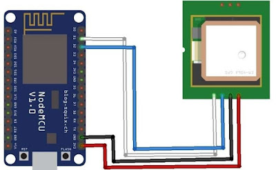
Connection
of LED:
Led have two
terminals, first is positive terminal and second is Negative Terminal. The Negative
Terminal is connected to the Ground pin of ESP8266 module and Positive Terminal
is connected to the 220ohm Resistance and the other side of resistance is connected
to the D2 pin of ESP8266 Module.
Circuit
Diagram:

Method to
Write code using TUNIOT:
Step1: search in browser TUNIOT.

Step2: open TUNIOT. Then, we see Two Blocks,
first block is Setup and Second Block is main Loop. In Left side given the blocks.

Step3: Now
first of All we disconnect network. GOTO—IOT—IOT status— Disconnect and arrange in Setup. Then, we add delay because, when network is disconnecting then our board is stable after sometime.
So, to add delay GOTO—IN/OUT—various—delayms.


Step4: Now Esp8266 Connect with a network. So, we use network ssid and password. So, GOTO—IOT—IOT Access Point—WIFI ssid and password block. And change ssid and password according to your WIFI network.

Step5: Now
print serial Monitor “WIFI is Connected”. So, GOTO—IN/OUT— Serial—select print
on new line and write in text menu “Connecting to WIFI “as shown in
figure.


Step6: when network is not found then our loop is continuously
found network.
So, GOTO—IOT—and
select Repeat While Block.

Step7: in while loop attach a block to print waiting
network in serial
Monitor. So, GOTO—IN/OUT—SERIAL—Select
Print on Same line. And text menu enters “…”.


Step8: when network is connected then our Serial monitor print
WIFI is connected. So, GOTO—IN/OUT—SERIAL—Select print on new line. And enter
in text column “WIFI is connected”.

Step9: when network is connected then our serial monitor print
WIFI IP address of the network. So, GOTO—IN/OUT—SERIAL—Select print on new
line. And delete the text bar of the block.
And then GOTO—IOT—IOT STATION—select LOCALIP.


Step10: To start server. So, GOTO—IOT—IOT-SERVER—and select START
SERVER PORT.


Step11:To setup the variable in starting the Setup. So,
GOTO—IN/OUT— string—Select declare String. Then, add a string value (text bar)
and it is equal to null. So, GOTO—TEXT—Select text bar.


All
above step are done in Setup.
Now,
set block in loop.
Step12: To wait a connection. So, GOTO—IOT—IOT-SERVER—Select WAIT SERVER.


Step13: then set String
Value. So, GOTO—IN/OUT—STRING—Select set string Block.

Step14: Read the value and equal to the string from the Server request.
So,GOTO— IOT—IOT-Server—Select
SERVER READ REQUEST.


Step15: ·
Then read HTTP request in the server. So, GOTO—IN/OUT—
STRING—Select HTTP SERVER REQUEST.


Step16:Then we Write Logic for HIGH and LOW condition. GOTO—LOGIC— select IF-DO block. And also select “= “block in
this step and attach with if- DO block
as shown in figure.


Step17: Now apply condition using variable. So, GOTO—IN/OUT—STRING—
Select “I “block and other side we attach a text block. So, GOTO—TEXT— Select
TEXT BLOCK as shown in figures.


Step18: In loop we attach pin of LED. So, GOTO—IN/OUT—DIGITAL—Select digitalWrite
block. and pin of ESP8266 Module in Block. and NOW attach Answer Mode. So, GOTO—IOT—IOT-SERVER—Select Answer
and enter text according to logic.


Step19: Now convert It into Program. In upper side you see Video
Icon and click on video Icon as shown in
figure. When you click the video icon a Name bar is open then, enter name and
click Ok. After click on Ok your code is downloaded. After, downloading the
code open code in Arduino IDE.


Method
for Making App:
Step1: Search MIT App inventor in your browser and
open it.

Step2: Now click on Create apps! and make account
in MIT App Inventor.


Step3: when you make account then open a new
window. Now click on Start New Project.

Step4: Then enter your App Name and press Ok.

Step5: You see Your App Folder is Create. Then you click on app folder. you will see
a new window as shown in below figure.

Step6: Create an app for LED in this Window. First
of all, you select Layout.So, go to—layout—Select Horizontal Arrangement.
and open it in screen window and set width and Height of layout in the
right-side properties window According to your choice. Here I will Take 3
Layouts.


Step7: Now Click on Button and Attach in middle
layout and set Height, Width, Button Name and Background color of the button in
Properties Window.


Step8: Then You make 2nd Button (Led OFF)
using Above step

Step9: After Making Buttons. Attach a Label and
text Box in 3rd layout and change its name, Width and Height using
Properties window according to below image and Attach text box in web. So, Go
To- Connectivity- Select Web and drag it in text box. Then, web1 is shown in
below the screen. Web1 is the nonvisible components.


Step10: Replace the name of Text Box by the IP
Addresses using Components Window As shown in figure.

Step11: Now click On BLOCKs (present in Right-side
upper corner). In this window we set button Function According us using Blocks.

Step12: Now We add Function of both
Buttons. GOTO—Button1—And Select When Button1 click blocks. And follow same
procedure for button2.

Step13: Go to—Web1—Select Set Web1 URL to Block and
attached to above Blocks.

Step14: Now Go to—Built in—Text—Select JOIN Block
and Attached to URL block according to below figure.


Step15: GOTO—IP address—Select IP Address-Text Block
and attach to
Join block
according to figure.

Step16: Now attach a text bar with join blocks.
GOTO—TEXT—Select text bar block and fill the attached text box According to figure.


Step17: GOTO—Web1—Select call web1 get block and
attached to the above blocks according to below figure.


And now match
the details according to the above image.
Step18: Now convert it into app. Then click on Built
(present in upper side). After click on the built you have two option then you
select save .apk to my computer option. Now your app is downloaded.
This app is sent to your mobile phone and install it.

Step19: open Arduino IDE and Upload the code (made
by the above procedure using TUNIOT) and open Serial Monitor and Get IP
address. This Ip address is put on your Mobile Phone as shown in below figure
and pressed the button. You will see your Led behave according to
the button pressed.


Comments
Post a Comment